PUBLISHED ARTICLE / XUNPAN
How to Select a Right-Angle Power Cord: Start With the Available Space
“90-degree connector” is not a complete specification. Buyers must identify the angled end, cable exit direction, interface combination, and actual installation clearance.
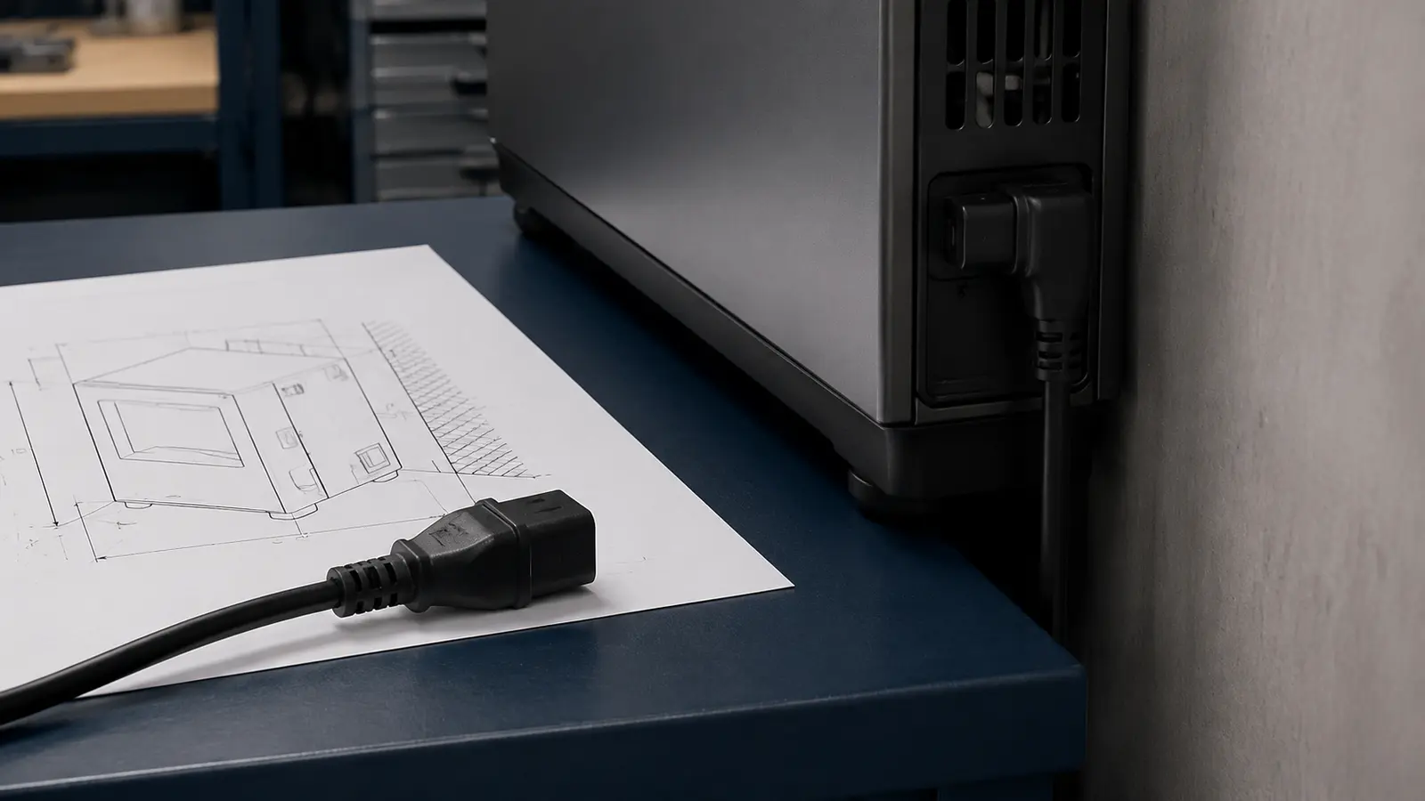
Imagine a compact appliance that must sit close to a wall. The plug and appliance connector are electrically appropriate, yet the straight connector body and the cable turn consume the available rear clearance. The enclosure has to move forward. A right-angle power cord may be a sensible direction, but “change it to 90 degrees” is still not a purchase-ready specification.
The angle may be at the wall plug or at the appliance connector. Even when two cords place the angle at the same end, one may route the cable up while another routes it down, left, or right. Those variants can produce very different installation results. Define both the angled end and the cable exit direction before treating a catalogue photograph as an approved configuration.
First identify which end is angled
An angled wall plug changes how the cable leaves the receptacle area. HSC’s current catalogue includes a 5-15P angled American three-prong power cord. Its specific product record lists UL and ETL. It is a useful starting point for discussing an angled North American wall end, but “angled 5-15P” alone does not define the finished cord.
At the appliance end, the available catalogue directions include an American 90-degree right-angle C7 connector power cord and a 90-degree right-angle American C13 connector power cord. Both current records list UL and ETL. An RFQ should state the wall plug and the appliance connector as one complete combination rather than name only one end.
Replace clearance guesses with one dimensioned view
Whether an angled configuration fits depends on the actual equipment layout, not on how compact it appears in a product image. A simple drawing with a datum and dimensions should answer at least four questions:
- Which sides of the receptacle or appliance inlet are obstructed by a wall, cabinet panel, wheel, guard, or another component?
- What is the available distance from the interface datum to the nearest obstruction?
- In which direction must the cable leave the molded body, and where does the cable route go next?
- Will an installer or service technician still have enough access to grip and disconnect the cord?
Add a cable-exit arrow and identify the viewing direction. That small detail reduces the familiar ambiguity in which a bend that looked left in a photograph routes right after installation. If the supplier needs a physical sample or 3D data to confirm the geometry, align those references before a trial build.
American and European angled cords do not share one specification
Right-angle and angled describe a physical layout. They do not select the destination-market plug, appliance connector, cable construction, or project documentation on the buyer’s behalf. A molded shape may fit the enclosure perfectly and still be the wrong finished-cord configuration.
For European-market discussions, HSC’s current catalogue includes European 90-degree C7 and European 90-degree C13 product directions. Their respective current records list VDE and ENEC. Like the American examples above, these records are starting points for a specific project discussion. Their certification fields apply to the individual product records; they should not be generalized to every right-angle power cord or every possible combination.
Market format is therefore only one layer of the RFQ. Use the equipment nameplate and engineering requirements to confirm the wall plug, appliance end, conductor specification, length, environmental conditions, and the certification or project documents applicable to the proposed model.
Three failure modes to catch early
A product photograph is supplied without an installation view. A photograph can identify the general form, but it may not establish left, right, up, or down once the cord is installed. A drawing with a datum, dimensions, and a cable-exit arrow is easier to review.
Only one end is specified. Neither “right-angle 5-15P” nor “right-angle C13” describes a complete finished cord. The opposite end, cable construction, length, and environmental conditions still need to be defined.
A mechanical benefit is treated as a certification conclusion. An angled connector may improve routing in one installation. That does not mean every angled cord is automatically more durable, safer, or suitable for a higher load. Those conclusions must come from the design, testing, and documentation for the proposed model.
Put these seven items in the RFQ
- Destination and use case: country or region, plus indoor or other relevant environmental conditions.
- Equipment information: nameplate data, appliance inlet, equipment drawing, or clear photographs.
- Complete interface combination: identify both the wall plug and appliance end; do not stop at “American cord” or “C13.”
- Angle definition: state which end is angled, the viewing direction, and where the cable must exit.
- Clearance and routing: critical dimensions, obstruction locations, cable path, and required service access.
- Cable and commercial inputs: conductor and jacket requirements from the engineering specification, overall length, color, quantity, and target timing.
- Documentation requirements: certification or other documents required by the destination market, customer project, and proposed model.
The purpose of these inputs is not to make the RFQ longer. It is to ensure that procurement, the equipment engineer, and the supplier are discussing the same finished-cord combination. Browse HSC’s power cords and plugs catalogue for current product directions, then send HSC the installation drawing, equipment information, and RFQ checklist for model-specific review.
This article provides general industry information. Specific technical requirements remain subject to the current standards and certification-body rules of the target market.
RELATED EVIDENCE